Measurements Modes
The instrument can simultaneously show any four of these outputs on the front panel display:
X In-phase
Y Quadrature
R Magnitude
ø Phase Angle
|
|
Noise |
| Harmonic |
nF, n≤ 65, 536 |
Dual Harmonic
Simultaneously measures the signal at
two different harmonics F1 and F2of the
reference frequency |
|
Dual Reference
Simultaneously measures the signal at
two different reference frequencies, F1
F2 where F1 is the external and F2the
internal reference |
|
| Frequency Range for Dual Harmonic and Dual Reference Modes |
F1 and F2 ≤ 20 kHz |
Virtual Reference
Locks to and detects a signal without a
reference (100 Hz ≤ F ≤ 250 kHz) |
|
Noise
Measures noise in a given bandwidth
centered at the reference frequency F |
|
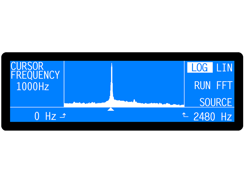
Spectral Display
Gives a visual indication of the spectral
power distribution of the input signal in a
user-selected frequency range lying
between 1 Hz and 60 kHz. Note that
although the display is calibrated in
terms of frequency, it is not calibrated
for amplitude. Hence it is only intended
to assist in choosing the optimum
reference frequency |
|
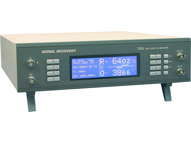
Display
240 x 64 pixel cold fluorescent backlit
LCD panel giving digital, analog bar-
graph and graphical indication of
measured signals. Menu system with
dynamic key function allocation. On-
screen context sensitive help |
|
| Signal Channel |
Voltage Input
Modes |
A only, -B only or Differential (A-B) |
| Full-scale Sensitivity |
2 nV to 1 V in a 1-2-5 sequence |
| Max. Dynamic Reserve |
> 100 dB |
Impedance
FET Input
Bipolar Input |
10 MΩ // 30 pF
10 kΩ // 30 pF |
| Maximum Safe Input |
20 V pk-pk |
Voltage Noise
FET Input
Bipolar Input |
5 nV/√Hz @ 1 kHz
2 nV/√Hz @ 1 khZ |
| C.M.R.R. |
> 100 dB @ 1 kHz |
| Frequency Response |
0.001 Hz to 250 kHz |
| Gain Accuracy |
±0.2% typ |
| Distortion |
-90 dB THD (60 dB AC gain, 1 khZ) |
| Line Filter |
attenuates 50, 60, 100, 120 Hz |
| Grounding |
BNC shields can be grounded or floated via 1 kΩ to ground |
| Current Input |
| Mode |
Low Noise or Wide Bandwidth |
Full-scale Sensitivity
Low Noise
Wide Bandwidth |
2fA to 10 nA in a 1-2-5 sequence
2 fA to 1 µA in a 1-2-5 sequence |
| Max. Dynamic Reserve |
> 100 dB |
| Frequency Response |
(-3 dB) |
Low Noise
Wide Bandwidth |
> 500 Hz
≥ 50 kHz |
Impedance
Low Noise
Wide Bandwidth |
< 2.5 kΩ ! 100 Hz
<250 Ω @ 1 kHz |
Noise
Low Noise
Wide Bandwidth |
13 fA/√Hz @ 500 Hz
1.3 pA/√Hz @ 1 kHz |
| Gain Accuracy |
± 0.6% typ, midband |
| Line Filter |
attenuates 50, 60, 100, 120 Hz |
| Grounding |
BNC shield can be grounded or floated via 1 kΩ to ground- |
| Reference Channel |
TTL input (rear panel)
Frequency Range |
0.001 Hz to 250 kHz |
Analog Input (front panel)
Impedance
Sinusoidal input
Level
Frequency Range
Squarewave input
Level
Frequency Range |
1 MΩ // 30 pF
1.0 V rms*
0.3 Hz to 250 kHz
250 mV rms*
2 Hz to 250 kHz |
| *Note: Lower levels can be used with the analog input at the expense of increased phase errors |
|
| Phase Set Resolution |
0.001º increments |
Phase Noise at 100 ms TC, 12 dB/octave slope
Internal Reference
External Reference |
< 0.001º rms
<0.01º rms @ 1 kHz |
| Orthogonality |
90º ±0.001º |
Acquistion Time
Internal Reference |
instantaneous acquisition |
| External Reference |
2 cycles + 50 ms |
| Reference Frequency Meter Resolution |
1 ppm or 1 mHz, whichever is the greater |
| Demodulator and Output Processing |
Output Zero Stability
Digital Outputs
Displays
Analog Outputs |
No zero drift on all settings
No zero drift on all settings
< 5 ppm/ºC |
| Harmonic Rejection |
-90 dB |
Output Filters
X, Y and R outputs only
Time Constant
Slope (roll-off)
All outputs
Time Constant
Slope |
10 µs to 640 µs in a binary sequence
6 dB/octave
5 ms to 100 ks in a 1-2-5 sequence
6, 12, 18 and 24 dB/octave |
| Synchronous Filter |
Available for F < 20 Hz |
| Offset |
Auto and Manual on X and/or Y: ±300% full-scale |
| Absolute Phase Measurement Accuracy |
≤0.01º |
| Oscillator |
Frequency
Range
Setting Resolution
1 mHz ≤ F ≤ 900 Hz
F . 900 Hz
Absolute Accuracy |
0.001 Hz to 250 kHz
1 mHz
4 mHz
± 50 ppm |
| Distortion (THD) |
-80 dB @ 1 kHz and 100 mV rms |
Amplitude (rms)
Range
1µV to 4 mV
4 mV to 500 mV
500 mV to 2 V
2 V to 5 V
Accuracy
> 1 mV
100 µV - 1 mV
Stability |
1 µV to 5 V rms
1µV
125 µV
500 µV
1.25 mV
±0.3%, F ≤ 60 kHz, ±0.5%, F > 60 kHz
±1%,F ≤ 60 kHz, ±3%, F > 60 kHz
50 ppm/ºC |
| Output Impedance |
|
Sweep
Amplitude Sweep
Output Range
Law
Step Rate |
0.001 to 5.000 V rms
Linear
20 Hz maximum (50 ms/step) |
Frequency Sweep
Output Range
Law
Step Rate |
0.001 Hz to 250 kHz
Linear or Logarithmic
20 Hz maximum (50 ms/step) |
| Auxiliary Inputs |
ADC 1 & 2
Maximum input
Resolution
Accuracy
Input Impedance
Smple Rate
ADC 1 only
ADC 1 and 2
Trigger Mode
Trigger Input |
±10 V
1 mV
±20 mV
1 MΩ // 30 pF
40 kHz max.
17.8 kHz max.
Internal, External or burst
TTL compatible |
ADC 3
Maximum input
Resolution
Input Impedance
Sampling Time |
±10 V
12 to 20 bit, depending on sampling time
1 MΩ // 30 pF
10 ms to 2 s, variable |
| Outputs |
Fast Outputs
Function
Amplitude
Impedance
Update Rate |
X and Y or X and Mag
±2.5 V full-scale; linear to ±300% full-scale
1 kΩ
166 kHz |
Main Analog (CH1 and CH2) Outputs
Function
Amplitude
Impedance
Update Rate |
X, Y, R, ø, Noise, Ratio, Log Ratio and User Equations 1 & 2.
±10.0 V full-scale; linear to ±120% full-scale
1 kΩ
200 Hz |
Signal Monitor
Amplitude
Impedance |
±10 V FS
1 kΩ |
Auxiliary D/A Outputs 1, 2, 3 and 4
Maximum Output
Resolution
Accuracy
Output Impedance |
±10 V
1 mV
±10 mV
1 kΩ |
8-bit Digital Output Port
8 TTL-compatible lines that can be independently
set high or low to activate exteranl equipment |
|
Reference Output
Waveform
Impedance |
0 to 5 V rectangluar wave
TTL-campatible |
| Power - Low Voltage |
±15 V at 100 mA rear panel 5-pin 180º DIN connector for powering SIGNAL RECOVERY preamplifiers |
Data Storage Buffer
Size
Max Storage Rate
From LIA
From ADC1 |
32k x 16-bit data points, may be organized as 1x32k, 2x16k, 3x10.6k, 4x8k, etc.
up to 1000 16-bit values per second
up to 40,000 16-bit values per second |
User Settings
Up to 8 complete instrument settings can
be saved or recalled from non-volatile
memory |
|
Interfaces
RS232 and GPIB (IEEE-488). A second
RS232 port is provided to allow "daisy-
chain" connection and control of up to 16
compatible instruments from a single
RS232 computer port |
|
General
Power Requirements
Voltage
Frequency
Power |
110/120/220/240 VAC
50/60 Hz
40 VA max |
Dimensions
Width
Depth
Height
With feet
Without feet |
13¼" (350 mm)
16½" (415 mm)
4¼" (105 mm)
3½" (90 mm) |
| Weight |
18 lb (8.1 kg) |